Directly from the manufacturer
Free delivery Australia wide
Fast delivery
Secure payment
Directly from the manufacturer

- Home
- Know How
- Thermal Imaging Camera
- Emissivity, RTC & IFOV: avoiding measurement errors in thermography | Testo
Emissivity, reflected temperature and IFOV:
How to avoid measurement errors in thermography

The greatest measurement errors in thermography are almost always caused by three variables: incorrectly set emissivity (ε), unconsidered reflected temperature (RTC), and a measurement distance at which the target is imaged too small in the thermal image (IFOV). If you consistently check and document these three points, thermograms become much more reliable – especially for metals, small components and changing environments.
Measurement object & measurement environment:
typical sources of error in thermography
First rule: a thermal imaging camera always shows the temperature of the visible surface – not the temperature under a cover or layer of dirt. For reliable temperature values, emissivity (ε) and reflected temperature (RTC) must match the surface and the measurement environment.
Material, colour, surface – what really matters
The colour of a surface has little practical influence on long-wave infrared radiation; temperature and surface condition are decisive. Smooth, glossy, reflective or polished surfaces usually have lower emissivity than matt, rough or weathered surfaces of the same material – and therefore reflect interference sources from the surroundings more strongly.

Emission, reflection, transmission – the three components of measured IR radiation
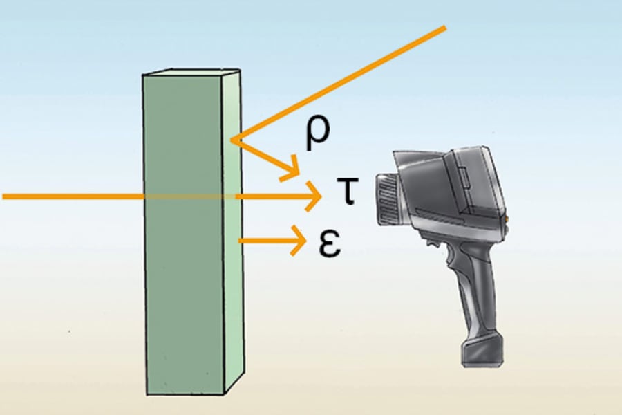
A thermography measurement physically consists of three components: emission (ε) from the measured object, reflection (ρ) of ambient radiation and, where applicable, transmission (τ) through certain materials. In practice, τ is almost 0 for most solid materials – exceptions include thin plastic films, for example.
Relationship between emission and reflection
For many surfaces, approximately: ρ = 1 − ε. Low ε means a high proportion of reflection – and therefore greater sensitivity to interference sources and incorrect RTC compensation.
Setting emissivity: understanding the typical direction of error
The direction of the measurement error depends on whether the measured object is warmer or colder than the surroundings.
ε set too high → temperature display too low
ε set too low → temperature display too high
ε set too high → temperature display too high
ε set too low → temperature display too low
Remember: the greater the temperature difference between the measured object and the surroundings and the lower ε is, the greater the measurement errors become – and they are amplified when ε is set incorrectly.
Using the emissivity table (reference values) correctly
Emissivity tables provide reference values: ε changes with temperature and surface condition, among other factors. Use table values as a starting point and, if necessary, validate them using a reference surface/reference method before documenting absolute temperature values.
Examples of typical reference values:
Concrete: ε ≈ 0,93
Glass (warm): ε ≈ 0,9
Aluminium (not oxidized): ε ≈ 0,02–0,03 (highly reflective → RTC/interference sources particularly critical)
Which three settings prevent the greatest measurement errors?
Set emissivity (ε) to match the material/surface,
take reflected temperature (RTC) into account when surfaces are reflective or the environment has strong temperature contrasts,
choose the measurement distance so that the target is imaged clearly larger than one pixel (IFOV).
In addition, focus and consistent scale logic ensure comparability.
Emissivity (ε): the most common reason for incorrect temperatures
Emissivity describes how effectively a surface emits IR radiation. Low ε means that a large proportion of the “seen” radiation is reflected from the surroundings. This can severely distort absolute temperature values – even if the thermal image looks “plausible”.
ε is between 0 and 1. High ε (e.g. many matt, non-metallic surfaces) is “forgiving” in thermography. Low ε (typical of bare metal) is critical because reflections dominate.
Measured values change significantly with viewing angle or location.
“Hotspots” appear, disappear or move.
The camera apparently shows the temperature of people, the sky or warm objects in the surroundings because they are reflected.
Practical measures include creating a suitable reference surface (e.g. a defined, well-emitting point), documenting measurement conditions (distance, viewing angle) and planning a comparative measurement (contact/another method) at critical points.
If you work with emissivity tables, use the values as a starting point and validate the result using a reference surface and reproducible measurement conditions. This prevents a “table value” from being mistaken for false precision.

Reflected temperature (RTC): when the surroundings contribute to the measurement
RTC is the effective ambient temperature that enters the measured value as a reflection. RTC is particularly relevant for reflective surfaces and when the surroundings are not “neutral” (e.g. warm machines, radiators, people nearby).
When RTC is particularly important
RTC is particularly important when:
the measured object is glossy/reflective,
the surroundings have strong temperature contrasts,
you use absolute temperatures or limit-value assessments.
Practical solutions: shading, viewing angle, constant environment
In practice, the following help: shading/shielding against interfering radiation sources, a viewing angle that is as constant as possible and a documented measurement position. The goal is not “perfection”, but reproducibility.
IFOV & measurement distance: when one pixel measures a mixed temperature
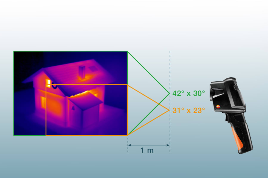
IFOV answers the question: is my target measurable at all from this distance with this optics? If a target is only one or a few pixels in size, the pixel inevitably contains background components – the measured value is a mixed temperature.
The principle: object size vs. pixel
A pixel is not a point, but represents an area/an angular range in the image. If the object is not imaged large enough, its informative value decreases. Small electrical connections, thin pipes or PV connections are particularly affected.
Practical rule for measurability (without false precision)
As a practical rule: the target should be clearly larger than a single pixel. If this is not possible, reduce the distance or choose optics/camera resolution that images the target larger.
Use IFOV tools
Tools help match object size, distance and camera configuration before measuring in the field.
Checklist for reproducible thermography
Define the measurement objective (object, distance, purpose: screening vs. absolute temperature).
Check and fix the focus.
Set ε appropriately (material/surface).
Check RTC (reflective scene? strong temperature sources in the surroundings?).
Check distance/IFOV: is the target large enough in the image?
Choose the scale mode consciously (fixed/auto) and keep it consistent for comparative measurements.
Document: distance, viewing angle, scale values, measurement points.
Practical example: glossy terminal in the switch cabinet
Error pattern: the terminal appears “hot”, but the hotspot shifts when the location changes. Interpretation: reflection dominates (low ε) and/or the target is too small (IFOV). Countermeasures: prepare the measurement location as a reference surface, stabilize the viewing angle, reduce the distance or use telephoto optics, check the focus and document measurement points consistently. Then verify the cause using suitable electrical measurements.
Next steps: choose technology and instrument features to suit your needs
Once ε/RTC/IFOV are understood as sources of error, camera selection can be better justified: resolution/optics suitable for the distance, NETD suitable for the contrast and workflow functions for documentation.
Do you have questions or would you like personal advice? Contact us!
We look forward to supporting you with our expertise and individual solutions.