
- Home
- Know How
- Thermal Imaging Camera
- How does a thermal imaging camera work? Explained simply | Testo
How does a thermal imaging camera work?
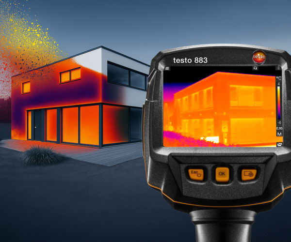
A thermal imaging camera captures infrared radiation (IR) from surfaces and converts it – together with measurement parameters such as emissivity (ε), reflected temperature (RTC), distance and focus – into temperature values for each pixel. The result is a thermogram that makes temperature distributions visible and can therefore quickly locate anomalies such as thermal bridges or hotspots.
What does a thermal imaging camera measure in practice?
In practice, the camera measures the radiation arriving at the detector from the field of view and derives surface temperatures from it. The measured value is therefore not the “pure temperature of the material”, but depends on the emission of the measured object, reflections from the surroundings and the imaging (object size vs. pixel/IFOV). To interpret thermograms correctly, these three influences must be considered consciously.
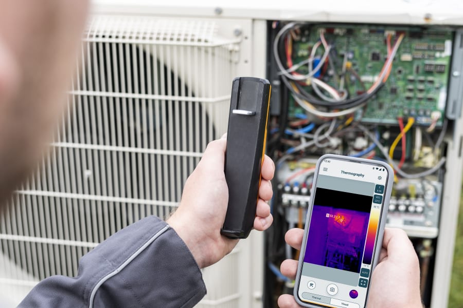
Basics: infrared radiation and thermogram
Thermography makes visible what the eye cannot see: long-wave infrared radiation. This radiation is electromagnetic and is emitted by surfaces depending on their temperature and material properties.
Why every object emits IR radiation
Every object above absolute zero emits thermal radiation. The higher the temperature, the greater the radiant power. For thermography, it is also important how “well” a surface emits or reflects – this is why two materials at the same temperature can appear differently.
From the IR signal to the image: detector, signal processing, colour scale
In the detector (often a microbolometer), incident IR radiation changes the electrical resistance of many small sensor elements. The camera electronics process these signals, correct them based on the set parameters and use them to create temperature values for each pixel. The colour scale then visualizes these values – it can enhance contrast, but does not change the physical basis of the measurement.

What the camera measures – and what it does not measure
A thermogram is a measurement image, but it remains a surface measurement under specific boundary conditions.
Surface temperature instead of “temperature inside the component”
A thermal imaging camera primarily measures surface temperatures. In the case of insulated pipes, multilayer components or air-flow constructions, the surface temperature can differ significantly from the temperature inside or from the medium temperature. Depending on the task, supplementary measurements are therefore useful for reliable diagnoses.
No ‘see-through’ through walls
Thermal imaging cameras do not “see through” solid, opaque building materials. They show temperature patterns on the surface. If something behind a wall heats up, it may be visible indirectly as a surface pattern – but this is not see-through; it is heat conduction/imaging at the surface.
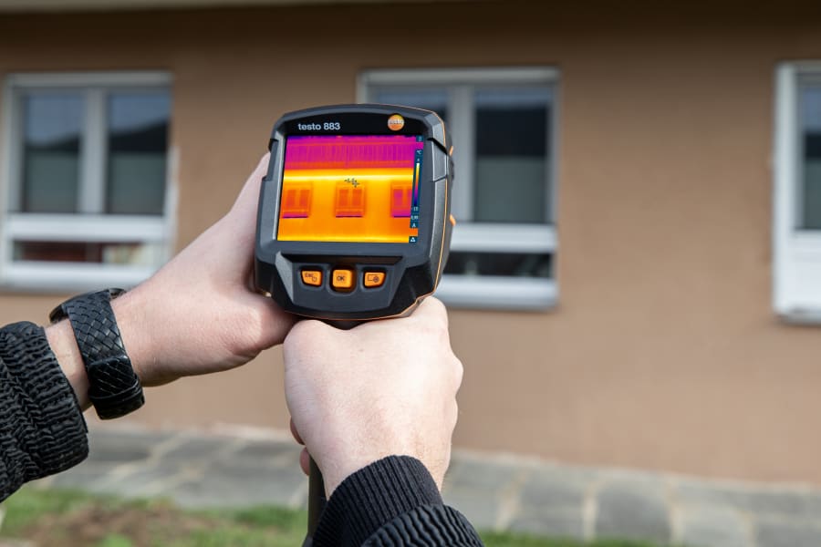
Why measurement parameters change temperature readings
Anyone who wants to use absolute temperatures (e.g. limit values, comparability) must actively set the measurement parameters. Without parameterization, many scenes can be interpreted as patterns, but the absolute values may be systematically inaccurate.
Emissivity (ε)
Emissivity describes how effectively a surface emits IR radiation. Low ε (typical of shiny metals) means: a lot of reflection, little emission. Without correction, the camera often does not measure the actual surface value, but a mixture of the object and the reflected surroundings.
Reflected temperature (RTC)
RTC describes the effective ambient radiation that is “reflected” on reflective surfaces and becomes part of the measured value. RTC is particularly relevant when the surroundings have strong temperature contrasts (e.g. warm machines, radiators, people) and the measured surface is reflective.
Measurement distance/IFOV and focus
A pixel always represents an angular range. If the measured object is imaged too small (distance too great, optics with too wide an angle), a mixed pixel consisting of the object and background is created. Incorrect focus also causes temperature information to be “blurred” – measurement points become unstable.
Practical example: why a hotspot sometimes “moves”
A typical misunderstanding in electrical thermography: a hotspot appears to shift when the perspective is changed. Common reasons are reflections on shiny surfaces (ε/RTC not suitable), a changed viewing angle, a different distance (IFOV) or a focus that is not exactly on the target. Practical tip: always perform comparative measurements with documented distance, a similar viewing angle and a consistent scale.
A thermal imaging camera displays temperature differences as a thermogram using infrared radiation and is therefore a measuring instrument for surface temperature patterns. A night vision device amplifies (depending on the technology) existing visible or near-infrared light to “see more” in the dark – but it does not provide temperature-based measurement information. For technical diagnostics (thermal bridges, hotspots), thermography is therefore the appropriate tool.

Next steps: avoid measurement errors, choose an application, select equipment
Once you understand how it works, the next steps are usually: (1) explore measurement parameters & typical sources of error in greater depth, (2) select your application and consider the boundary conditions, (3) choose a camera/optics suited to the object size and working distance.
Do you have questions or would you like personal advice? Contact us!
We look forward to supporting you with our expertise and individual solutions.