logo
  1. Home
  2. testo 310 II - with printer

testo 310 II - Flue gas analyzer with printer

0563 3105
  • Simultaneous, individual measurement and display of all relevant measurement parameters by (O2, CO, CO2, flue gas and ambient temperature, CO environment, draught and pressure). Display configurable via the testo Smart App
  • Simultaneous, additional measurements via the testo Smart App (e.g. gas flow pressure, flow and return temperature)
  • Easy and intuitive menu guidance
  • Digital documentation, data transfer and customer data management via testo Smart App
  • Heating fitters and technicians who perform commissioning and maintenance of hot water and residential heating systems need a reliable and stable measuring instrument with which they can easily perform their measuring tasks such as exhaust gas analyses. The new testo 310 II provides individual support for their daily measurement tasks and makes their day-to-day work easier.
    The testo 310 II has two measurement cells for O2 and CO, and a temperature sensor integrated into the flue gas probe. The gas sensors measure the exact oxygen and carbon monoxide content as well as the flue gas and ambient temperature. From these data, all relevant measurement parameters such as CO2 value, degree of effectivity and flue gas loss are calculated. In addition, the measuring instrument has its strengths in measurement accuracy, configurable measurement display, parallel measurement options, intuitive operation, sturdy housing, connection option to the testo Smart App: Our flue gas analyzer testo 310 II offers everything that heating fitters and technicians need for practical work on heating systems.


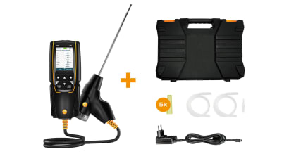
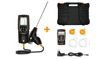
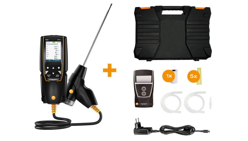
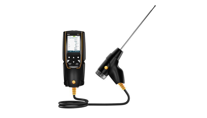
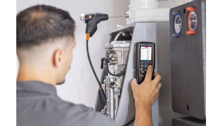
    Reliable testing of heating systems with the flue gas analyzer testo 310 II for beginners


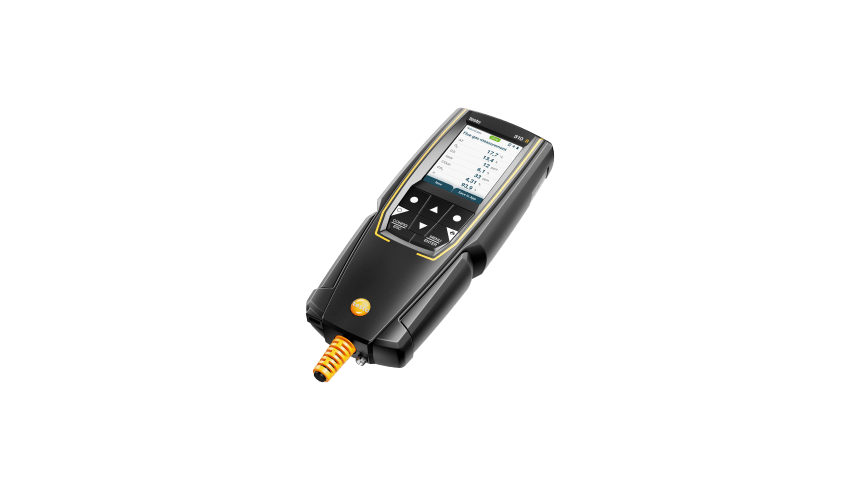
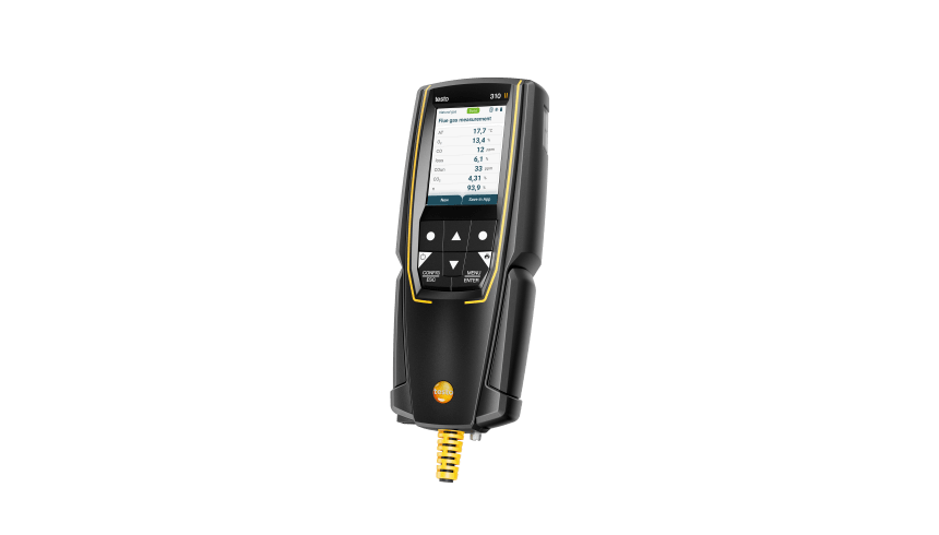
    The compact flue gas analyzer offers, in addition to the simple user interface, menu navigation with four integrated measurement menus for flue gas, draught, ambient CO and pressure. All measurement results are visible at a glance in the display and can be individually configured, thanks to the high-resolution graphic display.
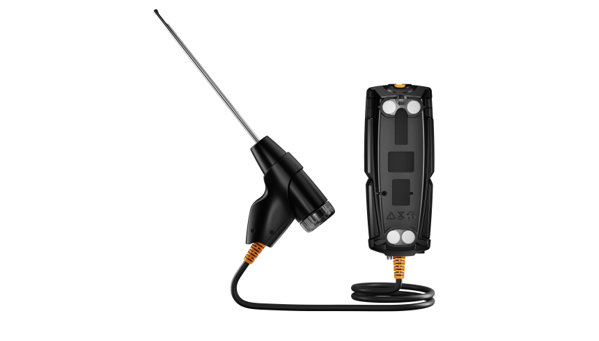
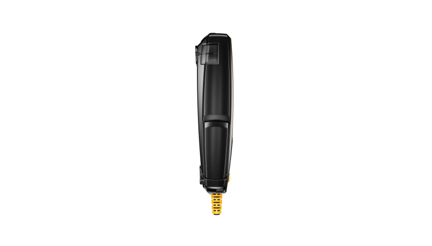
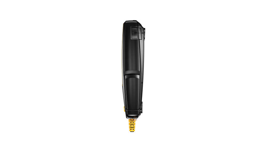
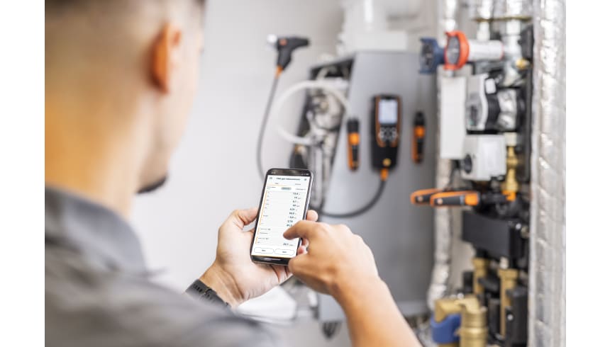
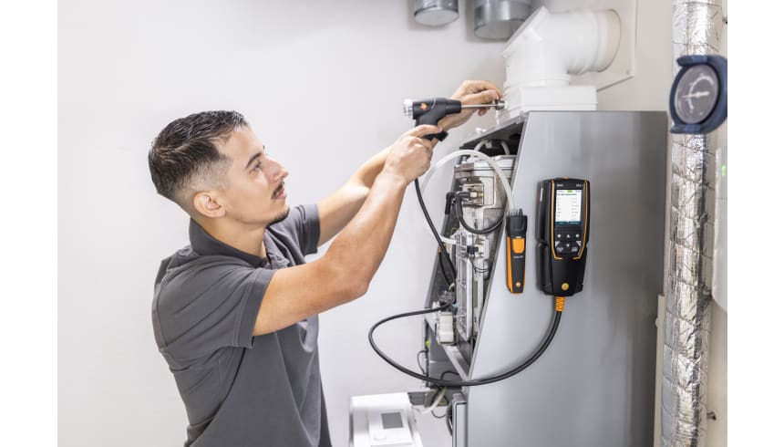
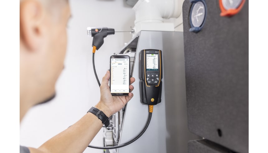
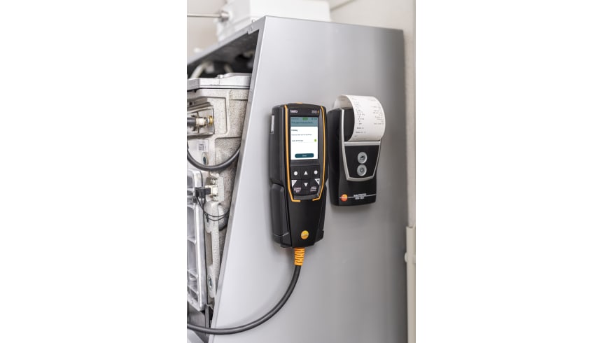
    If needed, you keep your hands are free during the measurement - because the flue gas analyzer testo 310 II can be fixed to metal surfaces, e.g. the burner, using the magnets on the back of the instrument. But this is not the only practical feature: The testo Smart App allows you to operate and configure your instrument via the remote function.
    The robust design for harsh, dirty environments, the fast sensor zeroing in 30 seconds, the easily replaceable probe filter and the condensate trap that can be emptied quickly make the flue gas analyzer the optimal tool for plant mechanics because it is cleverly designed.
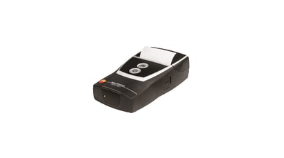
    If required, the measurement results can be transferred to the optionally available Testo quick printer via Bluetooth® interface or sent by e-mail and printed out directly on site.

    Flue gas analyzer testo 310 II incl. printer and calibration protocol for the measurement of O2, CO, hPa and °C, probe 180 mm with cone, silicon hose for pressure measurement, thermal paper, particle filters 5 off. and case

    Draught measurement in the flue gas duct

    Draught measurement is actually a differential pressure measurement. This differential pressure occurs between two sub-areas as a result of a difference in temperature. This is turn generates a flow to compensate. In the case of flue gas systems, the difference in pressure is an indicator of the “chimney flue draught”. This is measured between the flue gas and ambient air at the measurement orifice at the core of the flue gas flow.

    To ensure the flue gases are safely transported through the chimney there must be a differential pressure (chimney flue draught) for boiler systems that work with low pressure.

    If the draught is permanently too high, the average flue gas temperature increases and therefore flue gas loss. The level of efficiency drops.

    If the draught is permanently too low, oxygen may be lacking during combustion, resulting in soot and carbon monoxide. This will also cause a drop in the level of efficiency.

    Ambient CO measurement in the heated environment

    Carbon monoxide (CO) is a colourless, odourless and taste-free gas, but also poisonous. It is produced during the incomplete combustion of substances containing carbon (oil, gas, and solid fuels, etc.). If CO manages to get into the bloodstream through the lungs, it combines with haemoglobin thus preventing oxygen from being transported in the blood; this in turn will result in death through suffocation. This is why it is necessary to regularly check CO emissions at the combustion points of heating systems, and places often frequented by people (in our case, where the combustion systems for hot water generation are), and in the surrounding areas.

    Measuring the flue gas parameters of the burner (CO, O2, and temperature, etc.)

    The flue gas measurement for a heating system helps to establish the pollutants released with the flue gas (e.g. carbon monoxide CO) and the heating energy lost with the warm flue gas. In some countries, flue gas measurement is a legal requirement. It primarily has two objectives:

    1. Ensuring the atmosphere is contaminated as little as possible by pollutants; and

    2. energy is used as efficiently as possible.

    Stipulated pollutant quantities per flue gas volume and energy losses must never be exceeded.

    Measurement in terms of results required by law takes place during standard operation (every performance primarily using the appliance). Using a Lambda probe (single hole or multi-hole probe), the measurement is taken at the centre of flow in the connecting pipe (in the centre of the pipe cross-section, not at the edge) between the boiler and chimney/flue. The measured values are recorded by the flue gas analyzer and can be logged either for print out or transfer to a PC at a later stage.

    Measurement is taken by the installer at commissioning, and if necessary four weeks later by the flue gas inspector/chimney sweep, and then at regular intervals by the authorised service engineer.

    Measuring pressure on burners (nozzle pressure, gas flow pressure, etc.)

    Standard readings taken during services of domestic heating systems include checking the gas pressure on the burners. This involves measuring the gas flow pressure and gas resting pressure. The flow pressure, also called supplied pressure, refers to the gas pressure of the flowing gas and resting pressure of the static gas. If the flow pressure for gas boilers is slightly outside the 18 to 25 mbar range, adjustments must not be made and the boiler must not be put into operation. If put into operation nonetheless, the burner will not be able to function properly, and explosions will occur when setting the flame and ultimately malfunctions; the burner will therefore fail and the heating system will shut down.