1. Home
  2. testo 310

testo 310 - 냉난방 관리를 위한 연소가스 분석기

0563 3100
  • O2, CO, 연소가스 온도 및 대기 온도 동시 측정
  • 연소가스, 통풍, CO 주변 및 압력 측정 메뉴
  • 30초 이내에 센서 영점화
  • 최대 10시간 동안 사용할 수 있는 리튬형 충전가능한 배터리
  • 휴대용 프린터를 이용한 측정 데이터 인쇄
  • 내구성이 뛰어난 구조
  • 현장 전문가에게 적합하도록 설계된 연소가스 분석기 testo 310.
    정확한 측정값, 튼튼한 설계, 쉬운 사용
    여러분이 전문가로서 측정 도구에 바라는 세 가지 조건일 것입니다. 세가지 조건을 충족시켜야만 빠르고 믿을 수 있는 냉난방 시스템 관리가 가능합니다. 이것은 연소가스 분석기 testo 310으로 쉽고 빠르게 실현할 수 있습니다.


    냉난방 관리를 위한 연소가스 분석기 testo 310

    연소가스 분석기 testo 310은 쉬운 사용이 가능한 메뉴 가이드를 제공합니다. 연소가스, 노내압, 대기 CO, 압력 측정이 가능한 4개의 통합 메뉴와 읽기 쉬운 대형 백라이트 디스플레이는 여러분을 만족시켜 줄 것입니다.

    하지만 이것이 전부는 아닙니다. 연소가스 분석기 testo 310은 배관 및 냉난방 설비 전문가들을 위한 이상적인 동반자가 될 만한 조건들을 더 갖추고 있습니다. testo 310에는 자석이 내장되어 있어 버너 같은 금속 물체에 붙일 수 있습니다. 그렇기 때문에 다른 일을 할 때 여러분의 손은 무척 자유로워질 것입니다. 또한 센서 영점화가 30초 안에 완료될 뿐 아니라 센서 교체도 용이합니다. 어떤 충격에도 손상으로부터 보호하는 튼튼한 설계와 매우 신속하고 쉽게 비울 수 있는 내장형 응축트랩은 testo 310의 또다른 장점입니다.

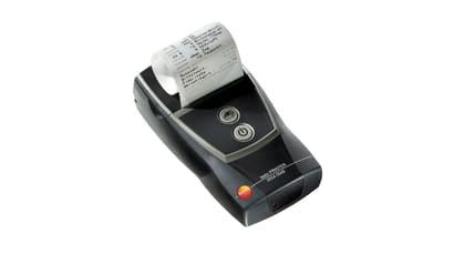
    마지막으로 측정값은 여러분의 테스토 프린터(별도 구매)로 보내 적외선 인터페이스를 이용해 현장에서 쉽게 출력할 수 있습니다.
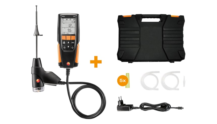


    상품 제공 시 포함

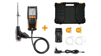
    연소가스 분석기 testo 310, 충전 가능한 배터리, 자체 교정 성적서, 압력 측정을 위한 실리콘 튜브, 프로브 필터 10개, 케이스.
     
     
    세트 제품번호
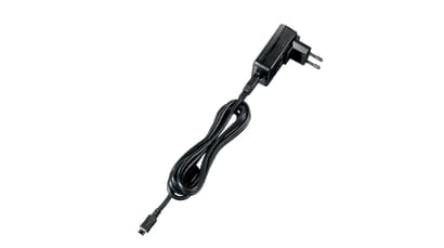
    ̉̇̈̉testo 310 기본세트
    testo 310 연소가스 분석기
    본체 일체형 프로브(180mm)와 케이스
    USB 전원 어댑터(케이블 포함)
    프로브 필터(10개)
    520563 3100


    • 연소가스 분석기 testo 310 본체 (O2, CO 센서, 연소가스 프로브 기본 장착)
    • 전원 어댑터
    • 프로브 핸들용 필터 (5개)
    • 차압 측정을 위한 실리콘 호스
    • 공장 성적서

    기술 데이터

    무게
    배터리 제외 700 g
    크기
    201 x 83 x 44 mm
    작동 온도
    -5 ~ +45 °C
    디스플레이 종류
    LCD
    디스플레이 기능
    백라이트 2라인 디스플레이
    전력 공급
    충전식 배터리 : 1500mAh; 전원 어댑터 5V/1A
    보관 온도
    -20 ~ +50 °C

    열전대K타입(NiCr-Ni)

    열전대 K타입 측정 범위
    -20 ~ +100 °C
    열전대 K타입 정확도
    ±1 °C
    열전대 K타입 분해능
    0.1 °C
    반응 시간 t99
    < 50 초
    온도(대기온도)

    열전대J타입(Fe-CuNi)

    열전대 J타입 측정 범위
    0 ~ +400 °C
    열전대 J타입 정확도
    ±1 °C (0 ~ +100 °C)
    ±1.5 측정값의 % (> 100 °C)
    열전대 J타입 분해능
    0.1 °C
    반응 시간
    < 50 초
    온도(연소가스)

    액세서리

  • 액세서리
    Spare particle filter
    분진 필터(10개)
      :
      0554 0040
    • 액세서리
      testo-Schnelldrucker IRDA mit kabelloser Infrarot-Schnittstelle
      테스토 적외선 고속 프린터
        :
        0554 0549
      • 액세서리
        Spare thermal paper
        프린터 용지
          :
          0554 0568
        • 액세서리
          USB의 전원 장치 포함. 케이블
            :
            0554 1105

          • Draught measurement in the flue gas duct

            Draught measurement is actually a differential pressure measurement. This differential pressure occurs between two sub-areas as a result of a difference in temperature. This is turn generates a flow to compensate. In the case of flue gas systems, the difference in pressure is an indicator of the “chimney flue draught”. This is measured between the flue gas and ambient air at the measurement orifice at the core of the flue gas flow.

            To ensure the flue gases are safely transported through the chimney there must be a differential pressure (chimney flue draught) for boiler systems that work with low pressure.

            If the draught is permanently too high, the average flue gas temperature increases and therefore flue gas loss. The level of efficiency drops.

            If the draught is permanently too low, oxygen may be lacking during combustion, resulting in soot and carbon monoxide. This will also cause a drop in the level of efficiency.

            Ambient CO measurement in the heated environment

            Carbon monoxide (CO) is a colourless, odourless and taste-free gas, but also poisonous. It is produced during the incomplete combustion of substances containing carbon (oil, gas, and solid fuels, etc.). If CO manages to get into the bloodstream through the lungs, it combines with haemoglobin thus preventing oxygen from being transported in the blood; this in turn will result in death through suffocation. This is why it is necessary to regularly check CO emissions at the combustion points of heating systems, and places often frequented by people (in our case, where the combustion systems for hot water generation are), and in the surrounding areas.

            Measuring the flue gas parameters of the burner (CO, O2, and temperature, etc.)

            The flue gas measurement for a heating system helps to establish the pollutants released with the flue gas (e.g. carbon monoxide CO) and the heating energy lost with the warm flue gas. In some countries, flue gas measurement is a legal requirement. It primarily has two objectives:

            1. Ensuring the atmosphere is contaminated as little as possible by pollutants; and

            2. energy is used as efficiently as possible.

            Stipulated pollutant quantities per flue gas volume and energy losses must never be exceeded.

            Measurement in terms of results required by law takes place during standard operation (every performance primarily using the appliance). Using a Lambda probe (single hole or multi-hole probe), the measurement is taken at the centre of flow in the connecting pipe (in the centre of the pipe cross-section, not at the edge) between the boiler and chimney/flue. The measured values are recorded by the flue gas analyzer and can be logged either for print out or transfer to a PC at a later stage.

            Measurement is taken by the installer at commissioning, and if necessary four weeks later by the flue gas inspector/chimney sweep, and then at regular intervals by the authorised service engineer.

            Measuring pressure on burners (nozzle pressure, gas flow pressure, etc.)

            Standard readings taken during services of domestic heating systems include checking the gas pressure on the burners. This involves measuring the gas flow pressure and gas resting pressure. The flow pressure, also called supplied pressure, refers to the gas pressure of the flowing gas and resting pressure of the static gas. If the flow pressure for gas boilers is slightly outside the 18 to 25 mbar range, adjustments must not be made and the boiler must not be put into operation. If put into operation nonetheless, the burner will not be able to function properly, and explosions will occur when setting the flame and ultimately malfunctions; the burner will therefore fail and the heating system will shut down.