1. Home
  2. testo  310 II

testo 310 II - 연소가스 분석기

0563 3104
  • 관련 측정치 일체를 동시 및 개별 특정하여 표시하고 (O2, CO, CO2, 연소 가스, 대기 CO농도, 노내압, 차압) Smart App을 통해 화면 표시 내용 간편 설정
  • testo Smart App을 통한 동시 및 추가 측정 (예: 가스 압력, 유속, 역류 온도)
  • 쉽고 직관적인 메뉴 안내 기능
  • testo Smart App을 통한 디지털 문서 작성 및 전송, 고객 데이터 관리 기능
  • 온수 및 주거용 난방 시스템의 작업과 유지 보수를 담당하는 난방 설비 기사 및 기술자는 배기가스 분석과 같은 측정 작업을 쉽게 수행할 수 있도록 안정적이면서도 신뢰할 수 있는 측정기가 필요합니다.
    새롭게 출시된 testo 310Ⅱ는 일상 측정 작업을 더 쉽고 원활하게 확인할 수 있도록 지원합니다.
    연소가스 분석기 testo 310 II는 난방 설비 전문가의 실제 작업에 필요한 모든 것을 제공합니다. 
    •  측정 정확도, 쉽고 직관적인 디스플레이, 견고한 기기, testo Smart App 연결 옵션
     

    연소가스 분석기 testo 310 II - 초보자를 위한 안정적인 난방 시스템 작업


    컴팩트한 연소가스 분석기는 간편한 기능과 더불어 연소가스, 풍속, 주변 CO 및 압력에 대한 4가지 통합 측정 메뉴를 포함한 기능을 제공합니다. 고화질 화면 표시 기능도 손 쉽게 활용이 가능합니다. 
    연소가스 분석기 testo 310 II는 기기 뒷면의 자석을 활용해 버너와 같은 금속 표면에 고정할 수 있어, 측정하는 동안 작업자가 자유롭게 움직일 수 있습니다. 이 뿐만 아니라, testo Smart App을 사용하여 원격으로 기기를 작동할 수 있어 더욱 편리합니다.
    거친 환경에서도 사용할 수 있는 견고한 설계, 30초 내의 빠른 센서 영점 조정, 쉽게 교체할 수 있는 프로브 필터 및 수분 응축 트랩 등 스마트하게 설계된 테스토 연소가스 분석기는 작업자에게 든든한 파트너가 되어줄 것입니다.
    특히, 블루투스 인터페이스를 통한 프린터 연결 기능을 탑재해 간단 명료한 보고서를 바로 인쇄하거나 메일로 전송할 수 있습니다.  

    testo 310 II 연소가스 분석기, 충전식 배터리 및 산소, 일산화탄소, hPa, 섭씨 온도 검교정 프로토콜, 콘(cone) 포함 180mm 탐침, 케이스, 전원 어댑터 및 케이블, 압력 측정용 실리콘 호스, 입자필터 5개, USB-C 케이블

    열전대K타입(NiCr-Ni)

    열전대 K타입 측정 범위
    -20 ~ +100 °C
    열전대 K타입 정확도
    ±1 °C
    열전대 K타입 분해능
    0.1 °C
    반응 시간 t99
    < 50 초
    온도(대기온도)

    열전대J타입(Fe-CuNi)

    열전대 J타입 측정 범위
    0 ~ +400 °C
    열전대 J타입 정확도
    ±1 °C (0 ~ +100 °C)
    ±1.5 측정값의 % (> 100 °C)
    열전대 J타입 분해능
    0.1 °C
    반응 시간
    < 50 초
    온도(연소가스)

    O₂측정값

    O₂ 측정
    0 ~ 21 Vol.%
    O₂ 정확도
    ±0.2 Vol.%
    O₂ 분해능
    0.1 Vol.%
    O₂반응시간
    30 초

    액세서리

  • 액세서리
    Spare particle filter
    분진 필터(10개)
      :
      0554 0040
    • 액세서리
      Spare thermal paper
      프린터 용지
        :
        0554 0568
      • 액세서리
        USB의 전원 장치 포함. 케이블
          :
          0554 1105

        • Draught measurement in the flue gas duct

          Draught measurement is actually a differential pressure measurement. This differential pressure occurs between two sub-areas as a result of a difference in temperature. This is turn generates a flow to compensate. In the case of flue gas systems, the difference in pressure is an indicator of the “chimney flue draught”. This is measured between the flue gas and ambient air at the measurement orifice at the core of the flue gas flow.

          To ensure the flue gases are safely transported through the chimney there must be a differential pressure (chimney flue draught) for boiler systems that work with low pressure.

          If the draught is permanently too high, the average flue gas temperature increases and therefore flue gas loss. The level of efficiency drops.

          If the draught is permanently too low, oxygen may be lacking during combustion, resulting in soot and carbon monoxide. This will also cause a drop in the level of efficiency.

          Ambient CO measurement in the heated environment

          Carbon monoxide (CO) is a colourless, odourless and taste-free gas, but also poisonous. It is produced during the incomplete combustion of substances containing carbon (oil, gas, and solid fuels, etc.). If CO manages to get into the bloodstream through the lungs, it combines with haemoglobin thus preventing oxygen from being transported in the blood; this in turn will result in death through suffocation. This is why it is necessary to regularly check CO emissions at the combustion points of heating systems, and places often frequented by people (in our case, where the combustion systems for hot water generation are), and in the surrounding areas.

          Measuring the flue gas parameters of the burner (CO, O2, and temperature, etc.)

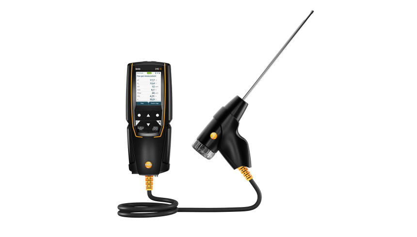
          The flue gas measurement for a heating system helps to establish the pollutants released with the flue gas (e.g. carbon monoxide CO) and the heating energy lost with the warm flue gas. In some countries, flue gas measurement is a legal requirement. It primarily has two objectives:

          1. Ensuring the atmosphere is contaminated as little as possible by pollutants; and

          2. energy is used as efficiently as possible.

          Stipulated pollutant quantities per flue gas volume and energy losses must never be exceeded.

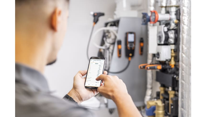
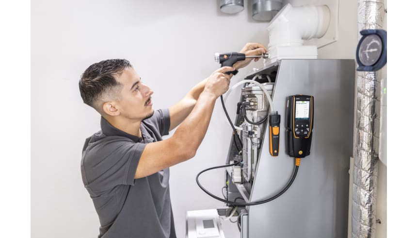
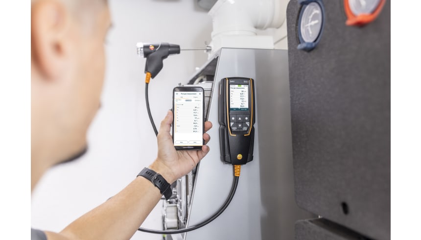
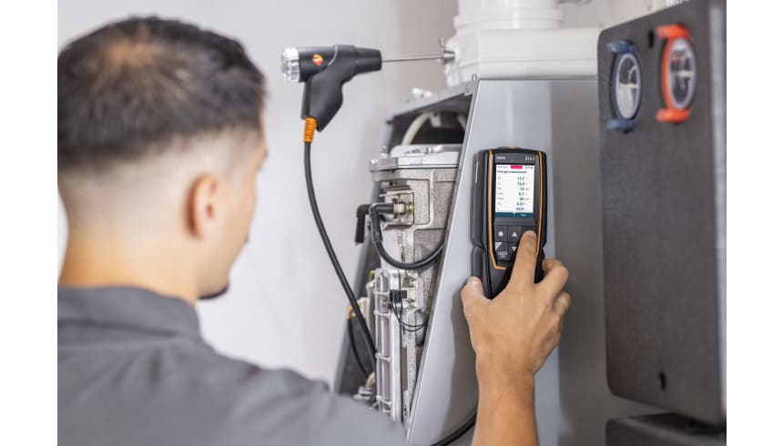
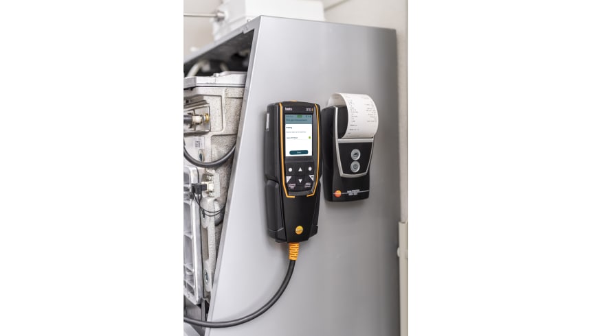
          Measurement in terms of results required by law takes place during standard operation (every performance primarily using the appliance). Using a Lambda probe (single hole or multi-hole probe), the measurement is taken at the centre of flow in the connecting pipe (in the centre of the pipe cross-section, not at the edge) between the boiler and chimney/flue. The measured values are recorded by the flue gas analyzer and can be logged either for print out or transfer to a PC at a later stage.

          Measurement is taken by the installer at commissioning, and if necessary four weeks later by the flue gas inspector/chimney sweep, and then at regular intervals by the authorised service engineer.

          Measuring pressure on burners (nozzle pressure, gas flow pressure, etc.)

          Standard readings taken during services of domestic heating systems include checking the gas pressure on the burners. This involves measuring the gas flow pressure and gas resting pressure. The flow pressure, also called supplied pressure, refers to the gas pressure of the flowing gas and resting pressure of the static gas. If the flow pressure for gas boilers is slightly outside the 18 to 25 mbar range, adjustments must not be made and the boiler must not be put into operation. If put into operation nonetheless, the burner will not be able to function properly, and explosions will occur when setting the flame and ultimately malfunctions; the burner will therefore fail and the heating system will shut down.