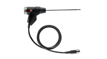
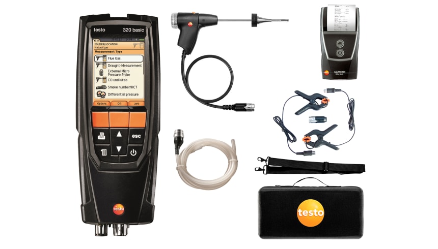
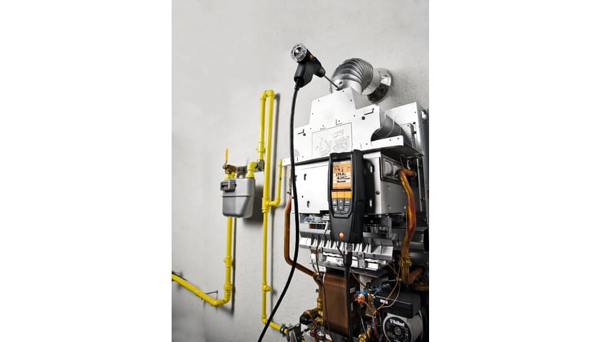
The testo 320 basic features all the essential functions for carrying out flue gas analysis on domestic heating systems, including flue draught, pressure measurements, and differential temperature measurement. The flue gas analyser is easy to use with its full colour graphic display featuring a user-friendly menu guidance. The analyser measures both O2 and CO (4,000ppm sensor fitted as standard) and can also display calculated parameters such as combustion ratio, CO2, etc.
testo 320B - Flue Gas Analyser (Advanced Set)
Order-Nr. 0563 3223 81
Details
Product Description
Overview
Advanced kit features include :
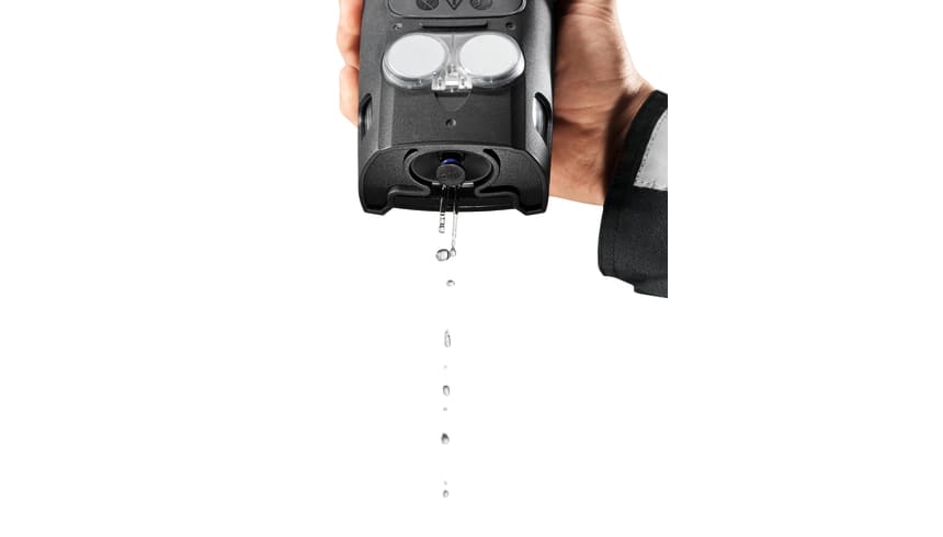
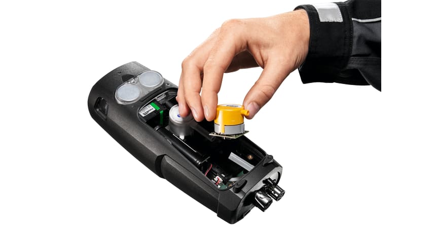
- 4,000ppm CO sensor with automatic pump shut off to help prevent saturation.
- 10 user selectable fuels
- rechargable Li-ion battery
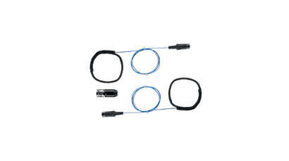
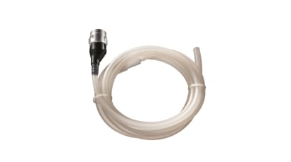
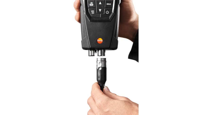
- Adaptors and accesories for pressure measurement, and differential temperature clamp probes supplied
- Testo IR printer
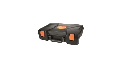
- Soft carry case with shoulder strap
- Independently tested according to EN 50379 Parts 1-3
Delivery Scope
Technical Data
General technical data | |
---|---|
Weight |
573 g |
Dimensions |
240 x 85 x 65 mm |
Operating temperature |
-5 to +45 °C |
Protection class |
IP40 |
Display size |
240 x 320 pixels |
Display function |
Colour graphic display |
Power supply |
Battery: 3.7 V / 2,400 mAh; Mains unit: 5 V / 1 A |
Memory |
|
Storage temperature |
-20 to +50 °C |
Flue gas O₂ | |
---|---|
Measuring range |
0 to 21 Vol.% |
Accuracy |
±0.2 Vol.% |
Resolution |
0.1 Vol.% |
Reaction time t₉₀ |
< 20 s |
Differential Pressure flue gas Draught - Piezoresistive | |
---|---|
Measuring range |
-9.99 to +40 hPa |
Accuracy |
±0.02 hPa or ±5 % of mv (-0.50 to +0.60 hPa) ±0.03 hPa (+0.61 to +3.00 hPa) ±1.5 % of mv (+3.01 to +40.00 hPa) |
Resolution |
0.01 hPa |
Temperature | |
---|---|
Measuring range |
-40 to +1200 °C |
Accuracy |
±0.5 °C (0 to +100.0 °C) ±0.5 % of mv (Remaining Range) |
Resolution |
0.1 °C (-40 to +999.9 °C) 1 °C (> +1000 °C) |
Flue gas degree of effectivity, Eta (calculated) | |
---|---|
Measuring range |
0 to 120 % |
Resolution |
0.1 % |
Flue gas loss (calculated) | |
---|---|
Measuring range |
0 to 99.9 % |
Resolution |
0.1 % |
Flue gas CO₂ calculation (calculated from O₂) | |
---|---|
Measuring range |
0 to CO₂ max (Display range) |
Accuracy |
±0.2 Vol.% |
Resolution |
0.1 Vol.% |
Reaction time t₉₀ |
< 40 s |
Pressure measurement | |
---|---|
Measuring range |
0 to +300 hPa |
Accuracy |
±0.5 hPa (0.0 to 50.0 hPa) ±1 % of mv (50.1 to 100.0 hPa) ±1.5 % of mv (Remaining Range) |
Resolution |
0.1 hPa |
Flue gas CO (without H₂-compensation) | |
---|---|
Measuring range |
0 to 4000 ppm |
Accuracy |
±20 ppm (0 to 400 ppm) ±5 % of mv (401 to 2000 ppm) ±10 % of mv (2001 to 4000 ppm) |
Resolution |
1 ppm |
Reaction time t₉₀ |
< 60 s |
Ambient CO | |
---|---|
Measuring range |
0 to 4000 ppm |
Accuracy |
±20 ppm (0 to 400 ppm) ±5 % of mv (401 to 2000 ppm) ±10 % of mv (2001 to 4000 ppm) |
Resolution |
1 ppm |
Measuring rate |
< 60 s |
Probes
Flue gas probes
Order Number: 0600 9740
Further probes
Temperature probes
Order Number: 0554 1208
Accessories
Accessories
Order Number: 0554 1203
Applications
Ambient CO measurement in the heated environment
Carbon monoxide (CO) is a colourless, odourless and taste-free gas, but also poisonous. It is produced during the incomplete combustion of substances containing carbon (oil, gas, and solid fuels, etc.). If CO manages to get into the bloodstream through the lungs, it combines with haemoglobin thus preventing oxygen from being transported in the blood; this in turn will result in death through suffocation. This is why it is necessary to regularly check CO emissions at the combustion points of heating systems and the surroundings.
Measuring the flue gas parameters of the burner (CO, O2, and temperature, etc.)
The flue gas measurement for a heating system helps to establish the pollutants released with the flue gas (e.g. carbon monoxide CO or carbon dioxide CO2) and the heating energy lost with the warm flue gas. In some countries, flue gas measurement is a legal requirement. It primarily has two objectives:
- Ensuring the atmosphere is contaminated as little as possible by pollutants; and
- energy is used as efficiently as possible.
Stipulated pollutant quantities per flue gas volume and energy losses must never be exceeded. Measurement in terms of results required by law takes place during standard operation (every performance primarily using the appliance). Using a Lambda probe (single hole or multi-hole probe), the measurement is taken at the centre of flow in the connecting pipe (in the centre of the pipe cross-section, not at the edge) between the boiler and chimney/flue. The measured values are recorded by the flue gas analyzer and can be logged either for print out or transfer to a PC at a later stage.
Measurement is taken by the installer at commissioning, and if necessary four weeks later by the flue gas inspector/chimney sweep, and then at regular intervals by the authorised service engineer.
Measuring pressure on burners (nozzle pressure, gas flow pressure, etc.)
Standard readings taken during services of domestic heating systems include checking the gas pressure on the burners. This involves measuring the gas flow pressure and gas resting pressure. The flow pressure, also called supplied pressure, refers to the gas pressure of the flowing gas and resting pressure of the static gas. If the flow pressure for gas boilers is slightly outside the 18 to 25 mbar range, adjustments must not be made and the boiler must not be put into operation. If put into operation nonetheless, the burner will not be able to function properly, and explosions will occur when setting the flame and ultimately malfunctions; the burner will therefore fail and the heating system will shut down.
Measuring temperatures on radiators
When measuring the temperature on radiators, the flow and return temperatures are recorded in particular and assessed by the tradesman. The flow temperature is defined as the temperature of a thermal transfer medium (e.g. water) that the system is supplied with. The temperature of the medium flowing out of the system is accordingly called the return temperature. To prevent losses within the heat distribution system and achieve a better level of efficiency in modern, heating technology, spot recording of flow and return temperatures is necessary at certain radiator pipes or screw fittings. Implementation of relevant measures ultimately leads to hydraulic adjustment on the basis of knowledge about the flow and return temperatures. This defines a procedure with which every radiator or heating circuit of a flat radiator within a heating system is supplied at a set flow temperature with the precise amount of heat needed to achieve the ambient temperature required for the individual rooms. Flawed operating conditions will result in considerable excess consumption of electricity and heating energy.
Downloads
Manuals
Software
-
Firmware-Update (testo 320 basic) (v1.09, BIN, 12.353 KB) If the firmware update does not start under Windows 8.1 or Windows 10, a new bootloader must be installed on the measuring device once.
A description and all necessary files can be found under the search term: Update-Kit / Bootloader -
Update-Kit / Bootloader (V1.22, EXE, 381 KB) If the firmware update does not start under Windows 8.1 or Windows 10, a new bootloader must be installed on the measuring device once.
A description and all necessary files can be found under the search term: Update-Kit / Bootloader -
Excel Tool testo 320 basic (v1.0, EXE, 1.939 KB) Allows retrieval of the current values from your testo 320 basic into a Microsoft Excel worksheet. Required is a 32 bit installation of Microsoft Excel/Office, which usually also can be used on 64 bit operating systems without problems.
-
Download testo 320 firmware (V1.12, BIN, 13.053 KB) If the firmware update does not start under Windows 8.1 or Windows 10, a new bootloader must be installed on the measuring device once.
A description and all necessary files can be found under the search term: Update-Kit / Bootloader